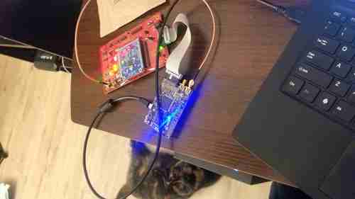
And all I got was this lousy board!
I actually had one of these during school as part of research, but had to give it up since I didn’t buy it. My student freeloading days are sadly over.
But money is handy so I got one.
NewAE provides tutorials to better learn the toolkit, and as I do the tutorials, I find they’re a bit too handwavy with the theory and the API they provide. Yes, it’s certainly nice I can just call scope.arm() and call it a day, but what does that really mean? So here’s some attempts at explaining.
Overclocking, or Fault Attack?
Most of this is basic info from any intermediate CompArch class but it bears repeating.
Electrons take time to move through stuff. This amount of time is a function of physical characteristics like medium, voltage, temperature, etc.

I like to imagine this as a race. A bunch of people go down all of these paths at the same pace, with a timekeeper keeping… uh, time, of how fast the people run. The amount of stuff that the red path goes through is much greater than, say, the blue path; in fact, the red path goes through the most stuff. Our timekeeper can thus only stop their watch according to the red path. We call this red path the critical path, and this is time that “officially” dominates how fast we can time something.
Officially is in quotes because there’s also some setup and winddown the runners have to do at the start and end of the race– various procedures to refine data. You may have to line up on a waterfall formation, crouch down at the line, etc, to fully get ready. Then, at the end of the race, you have to actually REGISTER (Ha!) the times somewhere, capture camera footage perhaps for close finishes, whatever. Thus, there is the time for the “official” race, but also the time to prime the runners and finish various bookkeeping elements.
Stepping away from my nostalgic analogy for my racing days, circuits are incredibly similar. Oftentimes at the start and end of our logic we will put registers, which themselves have lots of gates. Thus, practically speaking, the total time data flows through the circuit above is not just the red path, but also the time it takes for the inputs and outputs to be properly latched in registers.
This total time essentially formulates our overall timing constraints of our design, and this is why hardware has the various frequencies that it does. If we don’t follow this constraint, we run in to issues like data corruption and errors.
Overclockers may be familiar with this, and that’s why the world of competitive overclocking with esoteric cooling methods exist (and overvolting!). Crank up the voltage, or plummet the temperature, and our frequency can be increased.
The risks of fiddling with your chips’ clocks and voltages are well-known, in the best case resulting in aforementioned data corruption, and in the worst case a total bricking of your system, starting fires aside.
This is a Feature, Not a Bug
…at least depending on your perspective. (One could consider bricking a system a vulnerability using the CIA model!)
Consider the basic 5 stage CPU pipeline–

As an instruction flows between these pipeline stages, various timing constraints mentioned above have to be obeyed, or else… or else what? “Data corruption”, “undefined behavior”, “non-deterministic results” will be the usual language datasheets use, but the job of security is to think outside the spec.
So how might we tamper with the clock, and what happens?
We can craft a setup driving a non-periodic clock into our design, like so–

which is as simple as soldering an XOR gate to the clock pin and attaching our own hardware from there. Because most registers latch on the rising edge of the clock, this causes the resulting circuit to “double count” signals and fails to get propogated correctly to the next pipeline stage.
(Note: that this does imply that the ability of your hardware implies how precise you can cause glitches. i.e. a 5ghz CPU implies a need to match that frequency, somewhat.)

Because our pipeline is clocked at the rising edge, our timing constraint is not obeyed above, and our ALU for example might compute transient values.
Maybe this causes instructions to get improperly fetched from memory. Maybe this causes a deadlock. Maybe this causes a password entry to get bypassed.
I say maybe a lot, because as you can imagine, it requires very high precision to “double count”, and depends on how “far” data gets through the pipeline. Injecting a glitch while the CPU is stalled perhaps from some branch flush won’t do much, whereas skipping a cycle while data is getting marked as “retired” in a reorder-buffer would be bad news.
Ultimately, one has to identify the critical instructions, and then also toy with the exact location of an injection (or as one friends interprets it, “create an aftermarket Intel TM TurboBoost” without the self-regulating clocking logic to not brick or overheat itself).
In practice, the software window of opportunity can be reasonably large, and a little hardware knowledge can go a long way (looking at you Netburst with your 20 pipeline stages.) Let’s look at some examples.
Theory and Practice– A Simple Glitch
Lab 1: Simple Practice
This is mostly a guided walkthrough from NewAE’s tutorials here. Nothing technically impressive on my end.
Consider a super basic nested for loop like this. In terms of control flow, under typical program execution, we will basically always return 0 since the comparison cnt != 2500 will always be true. (In fact, your compiler may even optimize it out!)
The assembly for this might look like–

Above is some assembly of the linked C loop. In red is the accumulator that keeps track of cnt. In yellow is the loop counters. In blue is the entire basic block as a whole.
Now, first, consider our goal. Second, consider our window of opportunity, i.e. how probablistic it is to achieve our goal.
- Our goal is rather simple; just throw off the count. What looks suspiciously like the count? Why, the
addright at PC800_027a!- are there any other ways of throwing off the count? Sure! We could muck with the branch condition, or the memory accesses, or the comparisons, etc. Honestly pretty much anything I’ve marked in blue.
- To think more about opportunities, think about which instructions are critical to execution flow. All of the instructions in red definitely do. The instructions in yellow, only some– e.g. uxth doesn’t do much, nor does the load at PC
...0288.
Just looking at the first inner loop from PC_278 -- _28c(the sum of the red and yellow instructions), let’s assume they all take 1 cycle to execute. Given that this inner loop runs 2500 times, these 12 instructions take 30,000 cycles to execute, 4 of which are not useful if they glitch. This means that, for the inner loop, we have a 75% chance during 22500/30,000 cycles in which we can inject a glitch.- I would argue the odds are much greater than 75%, since the latency of each of those instructions is different from each other, but for simplicity let’s just say 1 cycle latency for each of them.
While extreme refinement is unnecessary here (all the function does is check cnt != 2500 to “pass”, making any injection at all that I mentioned above work), the primary purpose of the lab is an introduction that 1) injections are possible and 2) the method of refining and looking for viable glitch opportunities, as above.
Let’s look at what this actually means in code, as here. Lines 35 – 43 are the settings involved, and there’s an incredibly handy section of the lab that explains most of these settings.
clk_src > The clock signal that the glitch DCM is using as input. Can be set to “target” or “clkgen” In this case, we’ll be providing the clock to the target, so we’ll want this set to “clkgen”
offset > Where in the output clock to place the glitch. Can be in the range [-50, 50]. Often, we’ll want to try many offsets when trying to glitch a target.
width > How wide to make the glitch. Can be in the range [-50, 50], though there is no reason to use widths < 0. Wider glitches more easily cause glitches, but are also more likely to crash the target, meaning we’ll often want to try a range of widths when attacking a target.
output > The output produced by the glitch module. For clock glitching, clock_xor is often the most useful option.
ext_offset > The number of clock cycles after the trigger to put the glitch.
repeat > The number of clock cycles to repeat the glitch for. Higher values increase the number of instructions that can be glitched, but often increase the risk of crashing the target.
trigger_src > How to trigger the glitch. For this tutorial, we want to automatically trigger the glitch from the trigger pin only after arming the ChipWhipserer, so we’ll use ext_single
On line 57 we begin iterating over our width and offset “windows” chosen on lines 35 and 36. This refers to the parameters of our glitch.
Then, on lines 74 through 78 we actually launch the attack and probe the design for how it reacts.
The rest of the lines after line 78 is just more offline analysis and deserializing of the data returned by the design. The basic block at line 101 is where we actually check the payload to analyze the results.
Now you’re a hacker! :)
On Attack Methodologies
I find that these few steps are emblematic for how many attacks are.
Overall, you may notice our parameters on line 35 are rather large. This “brute forcing” is rather necessary, since there’s a fair amount of uncertainty with respect to actual hardware execution– branch stalls, cache misses, scheduling funkiness, etc. What matters more is the probability windows such that, if you formulate your glitch parameters correctly, you’ll (probably!) see results.
First, you really just have to do some trial and error– in testing terms, we need to define a proper stimulus. Where do we get the values [0, 20] and [0,10] for our clock width and offset? Really, it’s just a guess that we fine-tune. That’s why we have the for loop on line 57– we have some uncertainty still, partially because our window is ~75% and partially due to uArch behavior– so we craft a window of samples to overcome it.
Second, we have to have some mechanism to grab results– in verification, this might be called a monitor or generic “infrastructure”. Here the “results” is really just returned on the serial bus, but side-channels will not usually be so easy as a pure return value. Obviously useful for this lab to understand glitch attacks, but the level of abstraction here was hard to wrap my head around– I’m not used to just “poll ‘r’ for results”, but man would I wish I could just use python at work.
Third, some level of analysis of results has to be done– this might be called a checker. Here, this might involve some analysis of the design itself (we check if gcnt != 2500) and parsing the data to give it meaning. Simple enough here, but one can see how it can get difficult when you don’t have a super easy parsable JSON to play with.
Lab 2: password checker
This section is also a walkthrough of the lab here.
Consider a (barely) less naive example of a password check, where the window of opportunity isn’t so massive. What might the assembly look like?
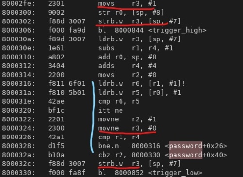
The primary loop that iterates over our password and user input is in blue, and the “return value” i.e. our password check value is in red. Those addresses are referenced via the 2 byte loads around PC 800_0316. Our “return value” first referenced at PC 800_02fe, and we can see via the red locations how that data value changes.
First– consider the goal– we are aiming to ensure our return value is 1 (which exists in memory address sp + 7/register r3). Second, consider the windows of opportunity in which that can happen.
- Where is the value modified? At PC
800_0324and800_032c, where there’s a conditional instruction and a store to our stack, respectively. If any of those instructions are dropped, we are good.- Our memory access can also be skipped via the branch at
032a. This checksr2, which is also modified by the conditional mov instruction. A similar case for our compare at0326. Seems like these compare instructions are quite important too! - It’s also feasible that, if we skip the first load at
0316, the subsequent comparison may set the flags, depending on the priorr6value.
- Our memory access can also be skipped via the branch at
- How likely are these opportunities? While there are several chances to make things go wrong (in point 1), the loop executes 5 times, and so we’d have to make whatever instruction(s) get dropped 5 times repeatedly. This is not impossible– we could tune our glitch parameters to repeat every N cycles. But it’s definitely harder.
Is there anything where we could possibly inject once to affect our return value? Yes! Right at032c, where the value gets pushed back on the stack. If we could tune our glitch to affect that window of instructions, this push would get skipped.
Firstly, when choosing our parameters, keep in mind that our ext_offset value is relative based on where our trigger occurs. E.g. since our trigger occurs at 0306, if we want to glitch, say, 032c, we’d have to inject an error ~15 cycles after our trigger. Again, this is approximate, because
there’s some uncertainty here. We got this number by, more or less, counting the delta between our trigger and end of our loop.
Additionally, if we only want to inject once, we want our injection to skip all the instructions on 0328, 032a, and 032c, since those branch instructions would loop back to the start of our loop, which we do not want.
Ultimately, there’s a lot of unknowns, so the solution here is just to have large windows and try lots of parameters! Below are some results of this brute forcing.
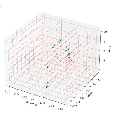
(I apologize for the overlapping data points around the ext_offset tickmarks. I’m a hardware guy, not a data visualization guy.)
The green indicates our design returned “1”, and red indicates either a crash or a return of “0”. We can see that, generally, for locations where we inject at 13 or 14 cycles after our trigger, we see a successful injection, and our theory matches up.
Because this is in a loop, we should see the same if we inject at ~15 + loop latency cycles as well, causing those same instructions to be skipped. So I ran for 4 more hours to see just that.
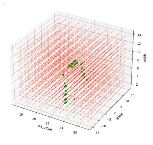
It’s a little difficult to see, but the green stars line up around values of ext_offset 23 and 24. Again, our theory matches up, and I’m positive if I had more patience I could repeat this probing to see this period of ~10 cycles show up.
Applying our attack methodology, we did the following–
-
Crafting our stimulus. If we were to have done full brute force, we’d have 3 dimensions to iterate over which is massive, so we narrowed down the number of tests we had to do with some a bit of binary analysis and knowledge of the hardware.
-
A mechanism to get results. Like Lab 1, it’s as simple as reading from the serial bus.
-
Analysis of results. Usually some data plotting and finangling, resulting in my beautiful plots above.
I’ve found that these steps are rather common in all security testing, and glitching is not majorly different. (Step 2 might involve giant oscilloscopes though!)
I aim to use this ChipWhisperer for more complicated projects. Given all the IoT things that exist around me, it’d be neat to get a better insight in to how they work, which was the main purpose for me buying this toolkit. Perhaps I’ll make more guided walkthroughs as I complete the tutorials.
Also, if I have to confess, my apartment key costs $50 to get a copy for, and I absolutely refuse to pay that for what amounts to a crappy birthday card microcontroller with a sensor, so naturally I spent $600 instead.